Wheel Hub
FSAE EV 2024 Front Wheel Hub
CAD
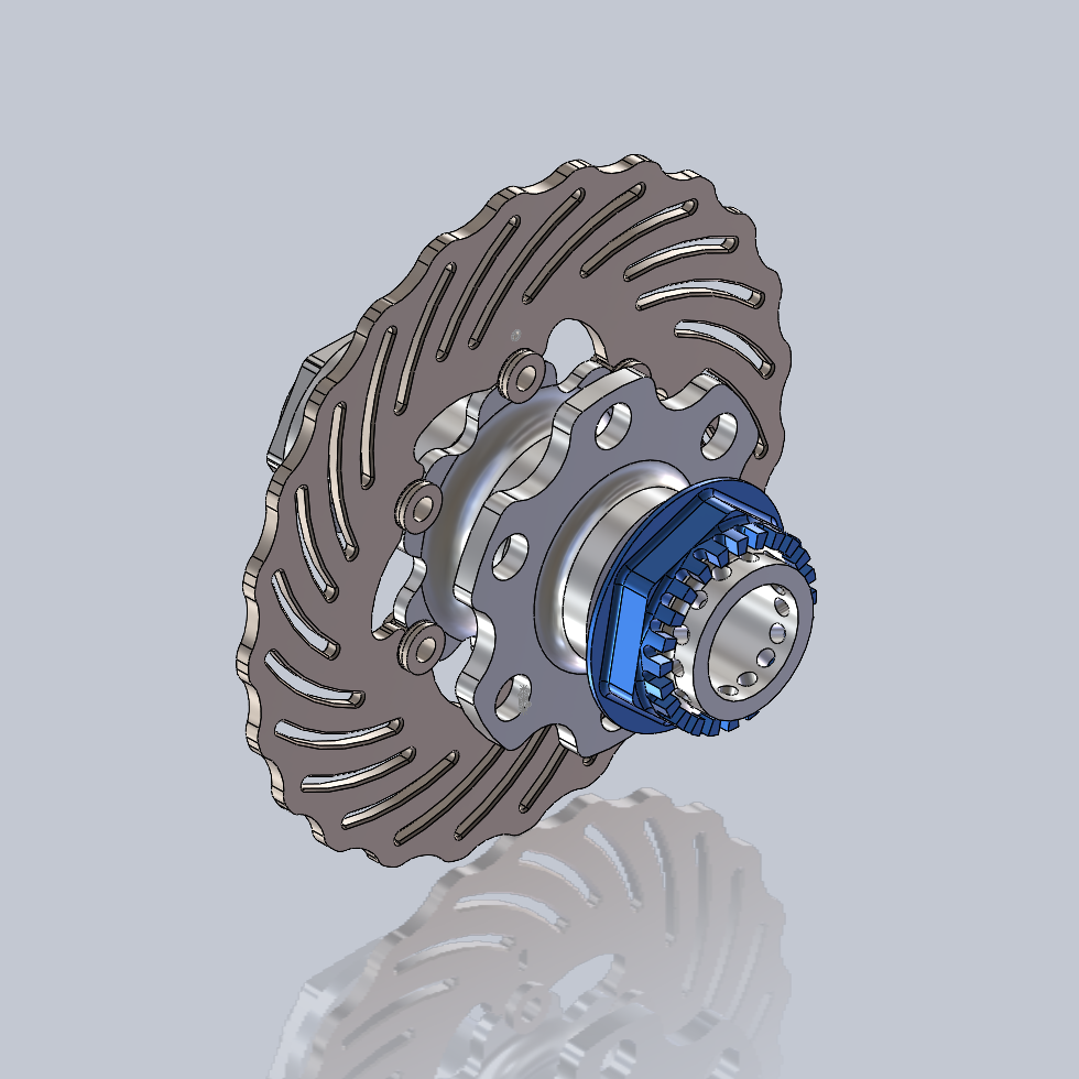
Front Wheel Hub (3D)
Design
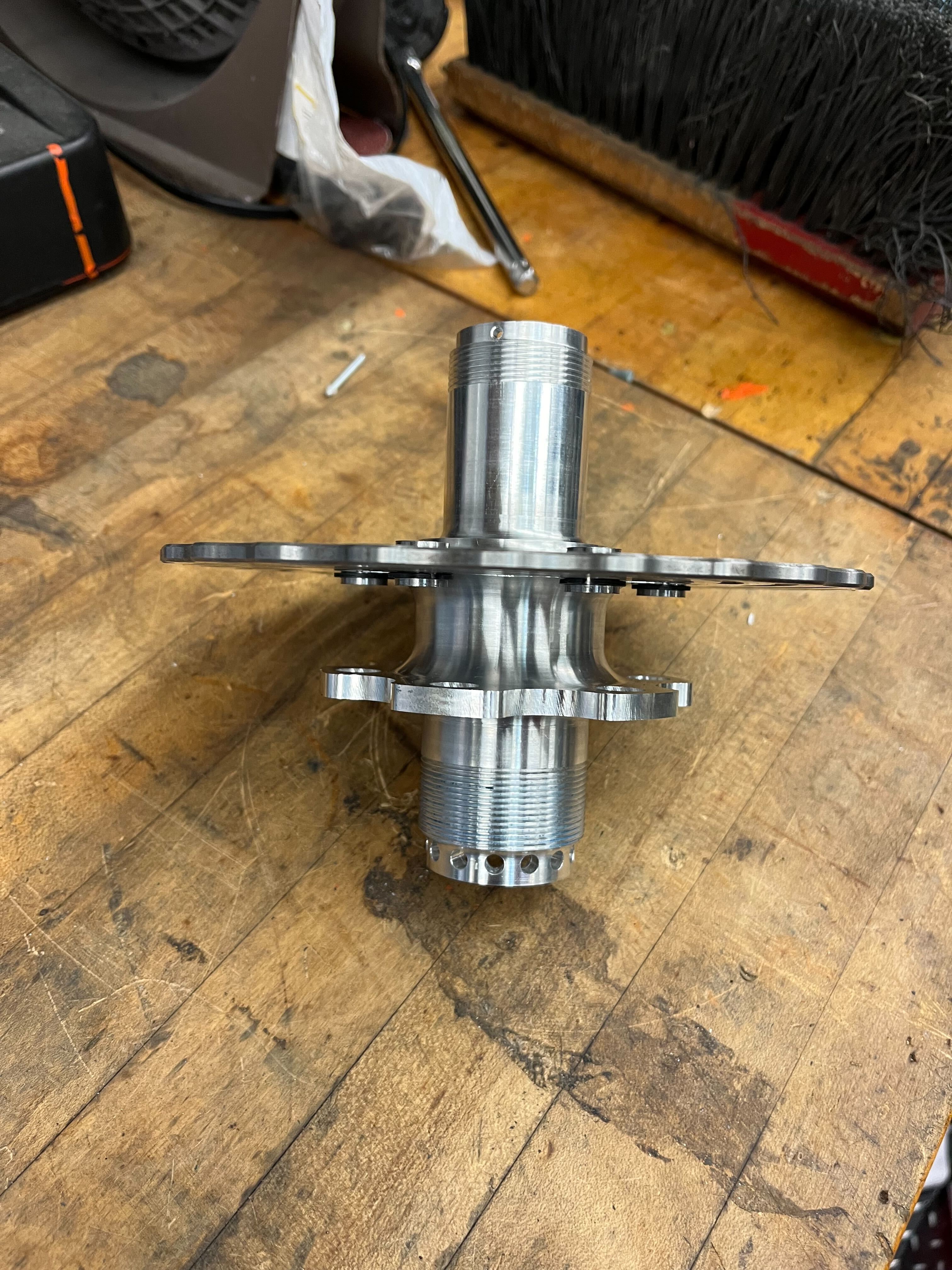
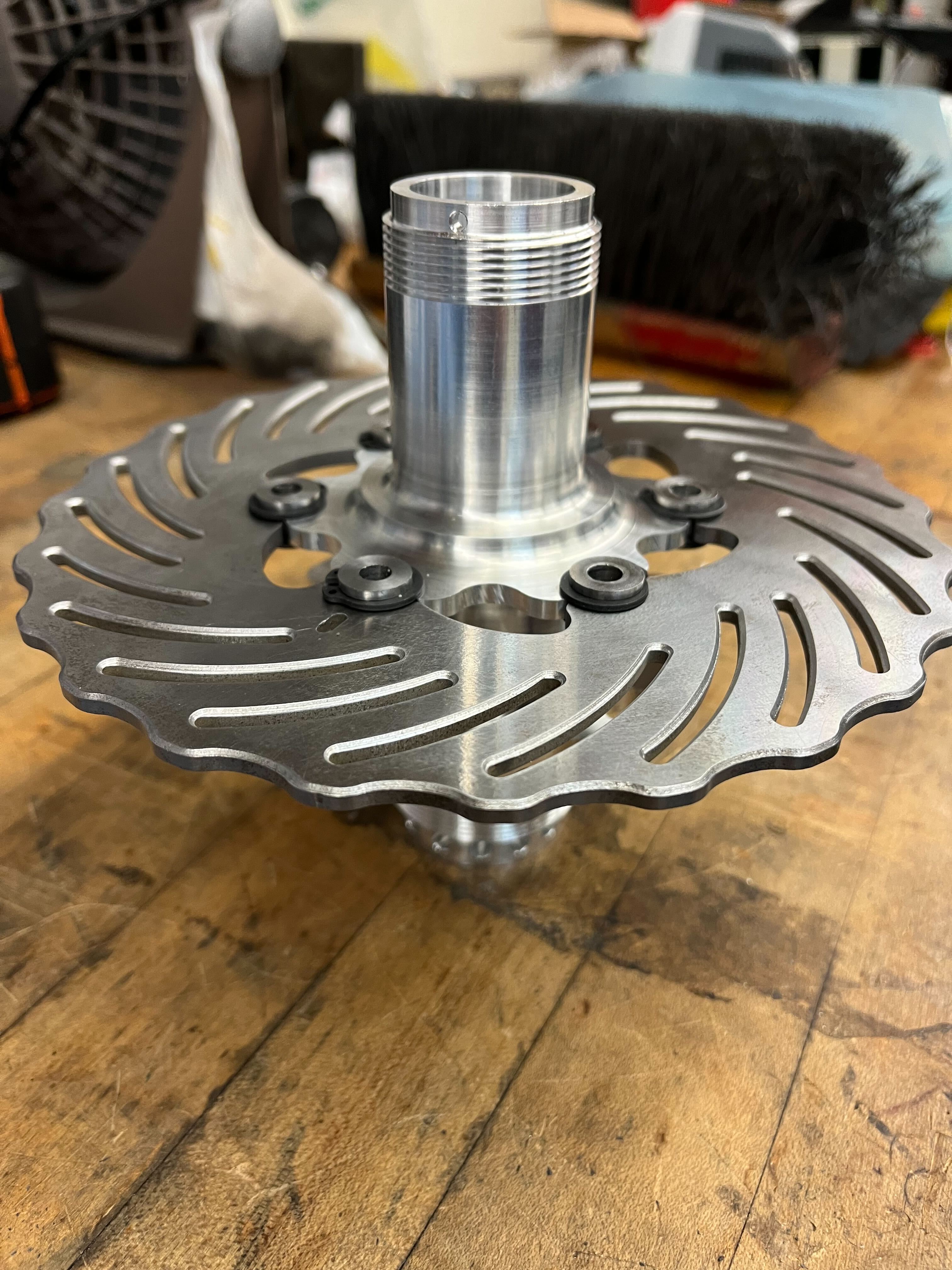
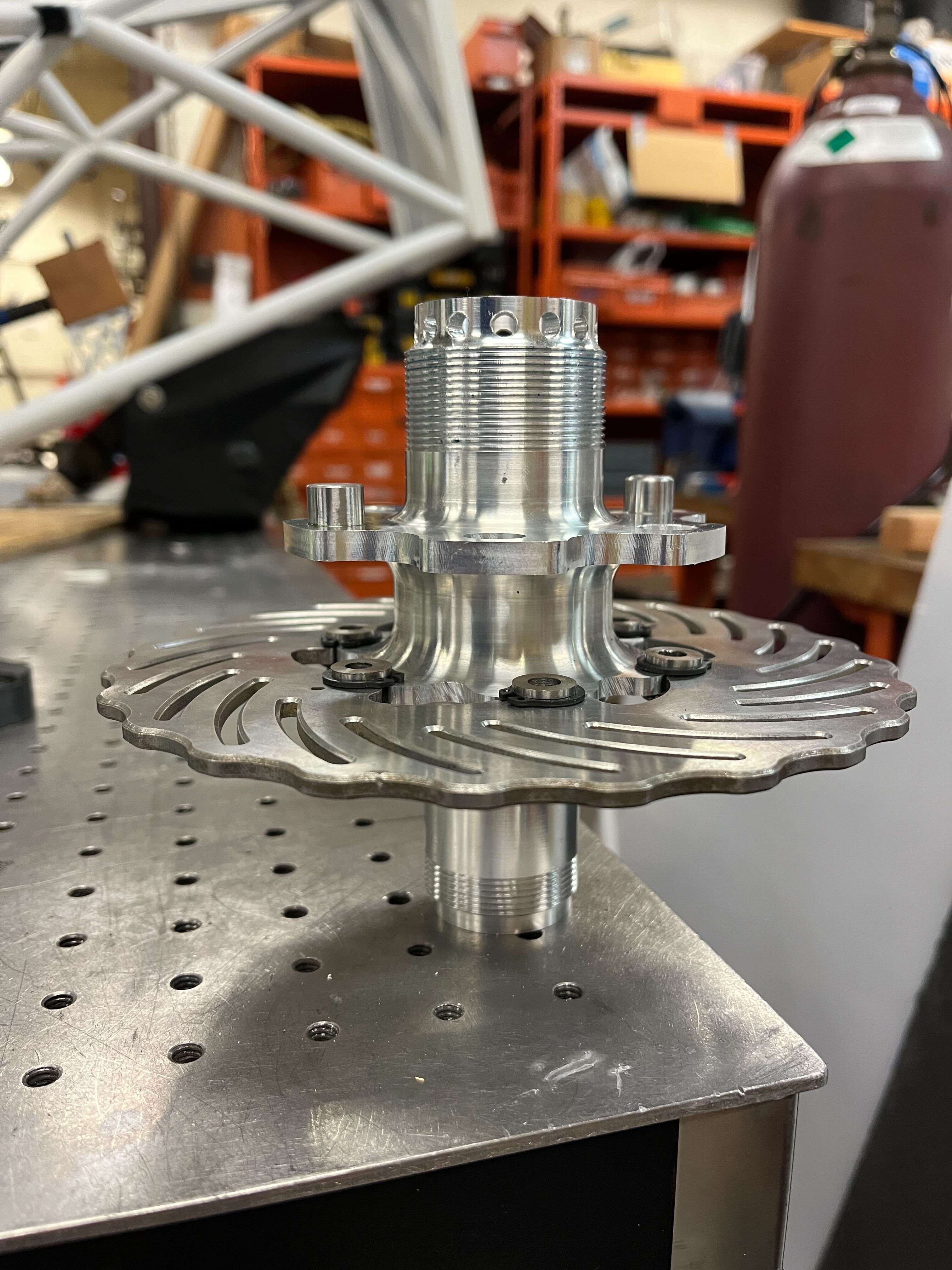
Front Wheel Hub Assembly (2023-24)
The front wheel hub's geometry was driven by two sources:
-
Wheel dimensions, set by the OZ Racing 10" CL wheels we chose due to the
weight savings and impressive price
-
Bearing size, which is determined by choosing from the options offered to
us for free from SKF Bearings
After establishing both of these parts as fit & function requirements, the wheel hub was developed
in iterations to minimize mass while passing FEA. This included loading in the following conditions:
-
Hard Braking (Torque transmitted through the Rotor mount flange)
-
Hard Acceleration (Torque transmitted through the Wheel mount flange)
-
Cornering (Axial force through the hub, transmitted via the preloaded bearings to the upright)
Material Selection
We chose Alumnimum 7075-T6 as it was familiar, machinable, and had a great strength-to-weight ratio. Although it lacks an endurance limit (as opposed to steel), this fatigue concern was largely irrelevant since the fatigue curve predicted failure in excess of $10^8$ cycles, which we did not expect achieve with our "100 miles before competition" internal target. Additionally, the thermal characterstics of 7075-T6 were acceptable. The yield strength of this material hits a "cliff" at $\sim 150^\circ C$, which is well outside reasonable operating temperatures. A bigger concern was the thermal expansion coefficient, at $2.3\frac{\mu m}{m-^\circ C}$. To ensure that heat conduction to the hub was minimal, we introduced thermal resistance between the brake rotor (the primary heat source) and the rotor mounting flange on the hub by floating the rotor with titanium brake buttons. This ensured no direct contact between the rotor and the hub, and with titanium having a low thermal conductivity of $6.7 \frac{W}{m-^\circ K}$, there were significant barriers to heat flow into the hub.
Calculations
Six Dowel pins were installed in shear to transmit torques from the wheel to the hub. Using the following equation: $$\tau_{pin} = \frac{F_L \times r_{tire}}{r_{pin}\times \text{\# of pins} \times \frac{\pi}{4}d_{pin}^2}$$ we can calculate the shear stress on any given pin, and to ensure that the reacting flanges don't tear out, we can use the following equation (utilizing some of the values calculated above): $$\sigma_{bearing} = \frac{F_{pin}}{d_{pin} \times \text{pin engagement}}$$ We use this "projected area" to account for the fact that the pin cannot pull the hub, it can only push, therefore a calculation with the full contact area would yield an incorrectly high FOS. To avoid this trap, we check the FOS using the projected area in hand calcs, and we then validate these calcs in ANSYS FEA.
Manufacturing
Front Wheel Hub Assembly (3D)